Measurements
/RF
Understanding S-Parameters: S11, S22, S12, and S21
An overview of S-parameters, including S11, S22, S12, and S21. Learn about their definitions, measurement setup, and what they reveal about a device under test.
3 min read
Advertisement
Table of Contents
This article provides a glossary of common terms used when working with scalar and vector network analyzers. We’ll cover concepts like transmission coefficient, insertion loss, gain, reflection coefficient, return loss, and S-parameters.
Let’s start by visualizing a typical network analyzer setup.
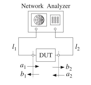
Figure 1: A network analyzer (specifically, a Keysight 8720D) is shown here, connected to a two-port Device Under Test (DUT). The diagram illustrates the incident wave (a1), transmitted wave (b2), and reflected waves (b1 and a2).
The transmission coefficient quantifies how much power successfully travels through the Device Under Test (DUT). It’s a ratio that essentially tells you the efficiency of power transfer.
Transmission coefficient = (2 * ZL) / (ZL + Zin)
Where:
Insertion loss measures the power lost when a signal travels through a passive component, such as a cable or a section of a circuit. It’s expressed in decibels (dB) and is always a negative value, signifying a decrease in power.
Insertion Loss (dB) = Output Power - Input Power
It’s important to note that the output power is always less than the input power in this scenario.
Gain, on the other hand, describes the increase in power as a signal passes through an active component, like an amplifier. Like insertion loss, it is measured in dB, but it will be a positive value, reflecting an increase in power.
Gain (dB) = Output Power - Input Power
In this case, the output power is greater than the input power.
The reflection coefficient indicates the amount of power that bounces back from the DUT, either at the input or output port. This occurs when there’s an impedance mismatch between the network analyzer and the DUT.
This is analogous to Ohm’s Law, where voltage is related to current and impedance (V=ZI). Here, we have:
Where:
Return loss is another way of expressing reflection. It quantifies how much power is not reflected back from the DUT and is also measured in decibels (dB).
Return Loss = -20 Log [abs(Reflection coefficient)]
S-parameters (Scattering parameters) are a set of values that describe how a network interacts with signals. In the two-port DUT scenario as in Figure 1, S-parameters are used to define the input and output characteristics of the device.
The basic equations for a two-port network are:
Where:
During typical measurements, the output port is terminated with a matched load (ZL = Z0), making a2 = 0. This simplifies the S-parameter equations to:
In this condition, S11 can be directly measured as the input reflection coefficient and S21 represents the transmission coefficient from port 1 to port 2. S22 can be similarly obtained, by inverting the port roles.
Advertisement
Measurements
/RF
An overview of S-parameters, including S11, S22, S12, and S21. Learn about their definitions, measurement setup, and what they reveal about a device under test.
Equipments
/RF
Explore the pros and cons of Scalar (SNA) and Vector (VNA) Network Analyzers for transmission and reflection measurements.
Terminology
/General
A breakdown of common decibel units used in RF and signal processing: dB, dBc, dBd, dBi, dBm, and dBW.