 T&M
T&M Voltage Doubler vs. Voltage Tripler vs. Voltage Quadrupler
Advertisement
This article compares voltage doublers, voltage triplers, and voltage quadruplers, outlining the differences between these voltage multiplier circuits.
What is a Voltage Multiplier?
A voltage multiplier is an electronic circuit that takes an AC waveform as input with a peak voltage (Vm) and produces a DC voltage output. The key feature of a voltage multiplier is that the output DC voltage is an integer multiple of the peak AC input voltage (Vm).
Voltage Doubler
Circuit and Operation
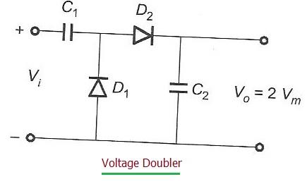
Figure 1 illustrates a typical voltage doubler circuit. As you can see, the input is an AC signal, and the output is a DC voltage. The primary function of this circuit is to approximately double the peak input voltage.
Output Voltage
The output DC voltage (Vout) is approximately equal to 2 * Vm, where Vm is the peak voltage of the AC input.
Voltage Tripler and Voltage Quadrupler
Circuit and Operation
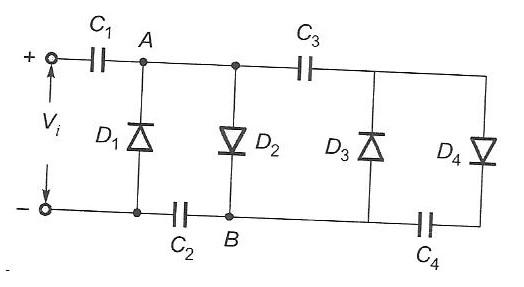
Figure 2 shows the circuits for both a voltage tripler and a voltage quadrupler. These circuits build upon the principles of the voltage doubler to achieve higher output voltages.
Output Voltages
- Voltage Tripler: A DC voltage of approximately 3 * Vm can be obtained across capacitors C3 and C1.
- Voltage Quadrupler: A DC voltage of approximately 4 * Vm can be obtained across capacitors C4 and C2.
In essence, these circuits use a combination of diodes and capacitors to progressively charge the capacitors and achieve the desired multiplication of voltage.
Advertisement


