Articles
/General
Microscope vs. Telescope: Understanding the Differences
Explore the differences between microscopes and telescopes, focusing on their purposes, magnification, and typical applications.
2 min read
Advertisement
Table of Contents
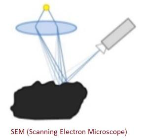
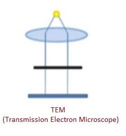
This article explores the key distinctions between two powerful tools in material characterization: the Scanning Electron Microscope (SEM) and the Transmission Electron Microscope (TEM). Both utilize electrons to generate images of samples, but they do so in fundamentally different ways, leading to distinct applications and results.
Electron microscopes have become indispensable for characterizing a wide variety of materials. Two primary types stand out: the Scanning Electron Microscope (SEM) and the Transmission Electron Microscope (TEM). While both use electron beams to create images, their methods of interaction with the sample and the information they provide differ significantly. Both SEM and TEM share some common components:
Think of an SEM image like the picture you see on a TV monitor, which is built up line by line.
A TEM image is similar to the image you might see on a fluorescent screen, where the electrons passing through illuminate the image directly.
The following table summarizes the core differences between SEM and TEM:
| Feature | SEM | TEM |
|---|---|---|
| Image Type | 3-Dimensional Image | 2-Dimensional Image |
| Beam Interaction | Scattered Electrons | Transmitted Electrons |
| Imaging Style | Direct Surface Imaging | Imaging Through Sample |
| Magnification | Up to 2 million | Up to 50 million |
| Resolution | 0.4 nm | 0.5 Å |
| Sample Area | Scans large areas | Scans thin samples |
| Limitations | Conducting samples, charging effect | Magnetic samples |
Advertisement
Articles
/General
Explore the differences between microscopes and telescopes, focusing on their purposes, magnification, and typical applications.
Articles
/Optics
A comparison of image intensifier and thermal imager technologies, highlighting their principles, applications, and differences.
Articles
/General
Explore the fundamental differences between analog and digital oscilloscopes, focusing on their operational principles and display methods.