Equipments
/Electronics
LED and Luminaire Test Equipment Overview
An overview of LED and luminaire test equipment, covering measurements, manufacturers, and key parameters. Essential for ensuring product quality and reliability.
3 min read
Advertisement
Table of Contents
This article explores the various tests and measurements used to assess the performance of LEDs, including the test setups used.
LED stands for Light Emitting Diode.
It’s made from a compound called gallium arsenide phosphide.
LEDs typically radiate infrared light at a wavelength of 850 nm.
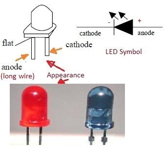
They have two leads: a longer lead called the “anode” (positive terminal) and a shorter lead called the “cathode” (negative terminal).
LEDs are commonly used as indicator lights in electronic devices and on circuit boards for debugging.
The figure below illustrates the appearance of an LED and its schematic symbol:
Here are some typical parameters measured during LED testing:
There are many video resources available online that provide tutorials on how to test LEDs. Here is a link to a Youtube video demonstrating basic LED testing using a digital multimeter.
The following figure-2 depicts a basic test setup used for verifying an LED, usually with a digital multimeter.
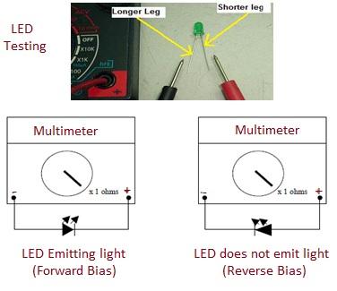
The procedure is relatively simple:
Advertisement
Equipments
/Electronics
An overview of LED and luminaire test equipment, covering measurements, manufacturers, and key parameters. Essential for ensuring product quality and reliability.
Measurements
/Electronics
This article covers zener diode testing, essential parameters, measurement techniques, test setups, and common failure modes to help evaluate these components.
Articles
/Electronics
This article explains how to identify open and shorted zener diodes using resistance and voltage tests with a multimeter.