Measurements
/General
Advantages and Disadvantages of Clamp Meters
This article explores the benefits and limitations of clamp meters, versatile tools used for electrical measurements, including current, voltage, and more.
3 min read
Advertisement
Table of Contents
This article explores the fundamental differences between current and voltage measurements, outlining the methods and equipment used for each. We’ll delve into how these measurements are performed and the crucial factors that ensure accuracy.
According to the principle of current continuity, current remains consistent throughout a single loop circuit. To measure current, we use an ammeter, which is always connected in series with the circuit element through which we want to measure current flow.
 Image alt: current measurement
There are two primary ways to measure current:
Contactless Method: This method leverages the magnetic field generated by current flowing through a conductor. The magnetic field causes a compass needle or similar indicator to rotate. While simple, this approach isn’t very precise, especially with low currents. It is generally more suited for measuring higher current values.
Using an Ammeter or Multimeter: This is the most common and accurate method. An ammeter utilizes the magnetic field produced by the current to deflect a needle on a scale. The deflection is directly proportional to the strength of the magnetic field, and thus the current. In circuit diagrams, an ammeter is represented by a circle containing the letter “A”.
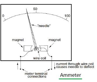
Image alt: Ammeter used for current measurement
How to use an Ammeter:
It is important to understand that the current measured by the ammeter is the same as the current flowing through the circuit element being measured. This method works for any circuit component, not just resistors.
Voltage, on the other hand, is measured across or in parallel with the circuit element of interest. We use a voltmeter for this purpose.
 Image alt: voltage measurement
When a voltmeter is connected to a circuit, a small current (Iv) flows through the voltmeter itself. According to the law of charge conservation, this small current reduces the current in the circuit, and can change the voltage V you are trying to measure. This is why it is crucial that the resistance of the voltmeter be significantly higher than the resistance of the circuit element being tested to have an accurate reading.
Here’s a breakdown of the key differences between ammeters and voltmeters:
By understanding these fundamental differences, you can accurately measure current and voltage, ensuring that your circuits function as expected.
Advertisement
Measurements
/General
This article explores the benefits and limitations of clamp meters, versatile tools used for electrical measurements, including current, voltage, and more.
Articles
/Electronics
Explore the differences between clamp meters and digital multimeters, focusing on their unique capabilities and applications in electrical measurements.
Equipments
/Electrical
An overview of digital clamp meters, highlighting their features, benefits, and differences from analog clamp meters. Includes example features of a Meco model.