Measurements
/RF
RF Coupler Testing: Specifications and Measurements
A guide to RF coupler testing, covering key parameters like coupling, directivity, insertion loss, and test setups. Learn how to measure these specifications.
4 min read
Advertisement
Table of Contents
RF mixers are critical components in RF and microwave systems, enabling frequency conversion for signal processing. Accurate testing and measurement are essential to evaluate parameters such as conversion loss, isolation, linearity and noise figure. This article explores key testing techniques, essential measurement parameters and the best equipment used for RF mixer evaluation.
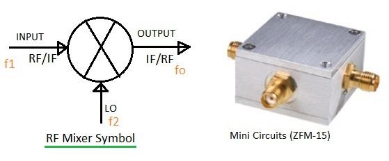
An RF mixer is a three-port device, typically labeled as RF, IF, and LO ports. It takes two input signals and produces a single output. This output usually contains the sum and difference of the input frequencies, leakage of the input signals, and harmonics of the inputs.
RF mixers are versatile devices with many applications. A very common one is frequency conversion, since mixers don’t alter the amplitude or phase of the input signals while shifting their frequency.
In RF down conversion, the difference between the input frequencies is extracted using an appropriate band-pass filter. The input ports are designated as RF and LO, while the output port is called IF.
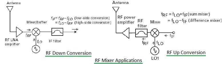
In RF up conversion, the sum of the input frequencies is selected using a band-pass filter. The input ports are IF and LO, while the output port is RF.
The following table outlines the generic specifications of an RF mixer that are verified during testing:
| RF Mixer Specifications | Description |
|---|---|
| Frequency of Operation | The manufacturer specifies the frequency ranges at the RF, LO, and IF ports for which the mixer is designed to operate. |
| Conversion Loss | This is the ratio of output power to input power, measured between the input and output ports. In decibels (dB), it’s the difference between output power (dB) and input power (dB). Conversion loss is a crucial parameter in RF mixer testing. |
| Noise Figure | This measures the noise added by the RF mixer during frequency conversion. For passive mixers, the noise figure equals the insertion loss, as these mixers do not provide gain. The Noise Factor = (Si/Ni)/(So/No). Noise Figure = 10 * Log10 (Noise Factor). |
| Isolation | Measured between the LO-RF or LO-IF ports. It indicates how much the local oscillator power leaks to the IF or RF port. In other words, it’s the attenuation of the LO signal as it travels to the other two ports. Manufacturers specify LO/RF and LO/IF isolation in datasheets, making it a critical parameter for both mixer selection and testing. |
| Dynamic Range | This is the range over which the RF mixer operates satisfactorily. The linear dynamic range is the difference between the input P1dB (the maximum signal level where the device operates linearly) and the MDS (Minimum Detectable Signal). The two-tone spurious-free dynamic range is defined as 2/3 * (Input_IP3 - MDS). |
| 1dB Power and Third Order Intercept (TOI) points | The 1dB compression point is where the output power stops increasing linearly with the input power. The input and output power levels at this point are the 1dB input/output powers respectively. The TOI point is typically 10 to 15 dB higher than the P1dB compression point. |
| Harmonic Suppression | Mixers produce sums, differences, and harmonics of input frequencies. It’s important to check the level of these harmonics. A certain amount of harmonic suppression is usually required to prevent them from interfering with the normal operation of the mixer. |
| Input and output VSWR or return loss | This measures how well the mixer ports reflect or pass signals. For example, to measure VSWR at the RF port, a signal is applied to the LO port, and the unused IF port is terminated with a 50-ohm impedance. |
These parameters are specified by RF mixer manufacturers in datasheets and manuals, which are important to consider when selecting a mixer.
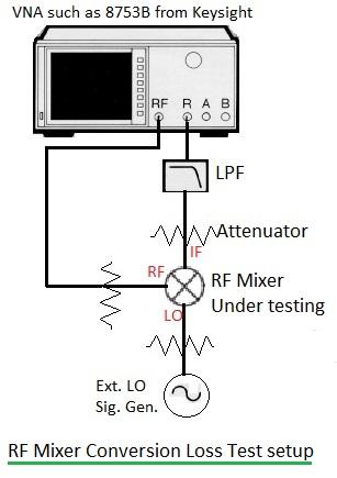
RF mixers are often tested using test jigs or dedicated PCBs with suitable dielectric materials. Figure 3 in the original article depicts a typical RF mixer conversion loss measurement using a Vector Network Analyzer (VNA). Other equipment that might be needed for RF mixer testing includes a spectrum analyzer for measuring harmonics and spurious signals, a power meter for P1dB and general power measurements, and a directional coupler for VSWR measurements.
Proper RF mixer testing ensures efficient frequency conversion, minimizes signal distortion and enhances overall system performance. By using the right measurement equipment and techniques, engineers can optimize RF mixer performance across various applications, including wireless communication, radar and satellite systems.
Advertisement
Measurements
/RF
A guide to RF coupler testing, covering key parameters like coupling, directivity, insertion loss, and test setups. Learn how to measure these specifications.
Measurements
/RF
This article provides a guide to testing RF circulators, covering key parameters, typical test setups, and specifications.
Measurements
/RF
Learn about RF isolator testing, key parameters like isolation, insertion loss, VSWR, and the typical test setup.