Equipments
/Electronics
Surge Generator Basics and Vendors
Learn about surge generators, their specifications, and key manufacturers. Essential for EMC testing and simulating high-energy interference pulses.
3 min read
Advertisement
Table of Contents
Grounding is a fundamental concept in electrical engineering, crucial for safety and proper operation of electronic equipment. This article explores the basics of grounding, its purposes, and different grounding system types, including single point, multi point, and hybrid grounding. We’ll also look at common grounding methods and materials used in test and measurement equipment.
Essentially, grounding is the connection between an electrical circuit or piece of equipment and the earth, or another conducting body that acts as a substitute for the earth. The system or equipment connected in this way is said to be “grounded.” This connection can also be considered as the link between a circuit and its 0-volt reference.
Grounding serves several critical purposes:
There are three main types of grounding systems, each suited for different applications:
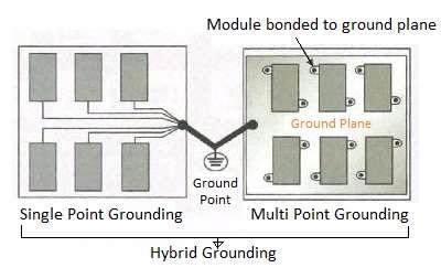
In single-point grounding, each subsystem or module has its own dedicated ground connection. All these individual grounds are then connected to a single system ground point using simple wires. This method is generally suitable for low-frequency analog circuits.
In multi-point grounding, each subsystem or module is directly connected to a common, low-impedance equipotential ground plane as directly as possible. This type of grounding is preferred for high-frequency digital circuits because metal sheets offer lower impedance at these frequencies.
Hybrid grounding is a combination of both single-point and multi-point grounding. Grounding points from both systems are connected to a common point. This method is commonly used in mixed-signal circuit designs, which involve both analog and digital circuits, and therefore both low- and high-frequency components.
The following table outlines various grounding methods and materials commonly used in test and measurement equipment. This is often referred to as the “grounding hierarchy” and is essential for proper equipment installation.
| Equipment Type | Grounding Method/Material |
|---|---|
| Low Level, Low Frequency | Simple wire can be used for grounding, typically up to a few kHz. |
| Low Level, High Frequency | Mesh is used for grounding, offering low inductance; suitable up to tens of MHz. |
| High Level, High Frequency | Flat metal strips to the ground plane are used, for applications up to hundreds of MHz. |
The ground hierarchy also includes grounds for cables, transformer shields, DC returns, lightning protection, and AC power safety.
In conclusion, selecting the right grounding method is essential for the proper functioning and safety of electrical and electronic systems. Understanding the differences between single-point, multi-point, and hybrid grounding, as well as the materials and methods involved, is crucial for engineers and technicians alike.
Advertisement
Equipments
/Electronics
Learn about surge generators, their specifications, and key manufacturers. Essential for EMC testing and simulating high-energy interference pulses.
Equipments
/Electronics
Learn about ESD ionizers, their types, and how they work to neutralize static charges, protecting sensitive electronic components from electrostatic discharge damage.
Articles
/General
Explore EMI and EMC testing concepts, standards, and prominent service providers. Learn about radiated and conducted emissions, immunity testing, and more.