Articles
/General
Understanding EMI/EMC Testing and Service Providers
Explore EMI and EMC testing concepts, standards, and prominent service providers. Learn about radiated and conducted emissions, immunity testing, and more.
3 min read
Advertisement
Table of Contents
This article clarifies the distinction between EMC (Electromagnetic Compatibility) measurement and EMI (Electromagnetic Interference) measurement. While often used interchangeably, there are subtle differences. It’s crucial to understand these distinctions, especially when dealing with compliance testing. For commercial applications, receivers must adhere to CISPR Part-16 standards, while military applications require compliance with MIL-STD-461. CISPR 16-1-1 specifies that a receiver should operate within a frequency range of 9 kHz to 18 GHz, with an absolute accuracy of about +/-2dB, among other requirements. Companies like Keysight Technologies develop specialized EMI/EMC equipment to meet these needs.
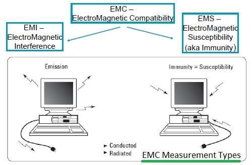
Figure 1 illustrates the four main types of EMC measurements:
Importantly, EMI measurement falls under the broader umbrella of EMC measurement.
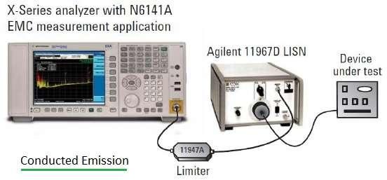
The following steps are generally followed during a conducted emission EMC measurement (as shown in Figure 2):
Here are general guidelines for conducting EMI measurements on a DUT:
Both Radiated Immunity and Conducted Immunity tests are considered under EMI measurements.
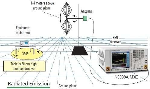
Figure 3 illustrates a typical radiated emission test setup. The process generally involves:
In summary, while the terms are related, EMC encompasses a wider range of testing and compliance, while EMI focuses more specifically on identifying and mitigating sources of electromagnetic interference.
Advertisement
Articles
/General
Explore EMI and EMC testing concepts, standards, and prominent service providers. Learn about radiated and conducted emissions, immunity testing, and more.
Equipments
/Electronics
Overview of near-field probes, including their types (H-field and E-field), common applications in interference detection and shielding verification, and a list of manufacturers.
Articles
/Wireless
An overview of WiFi testing, covering radio conformance, protocol conformance, and interoperability. Essential for WLAN device manufacturers and software developers.